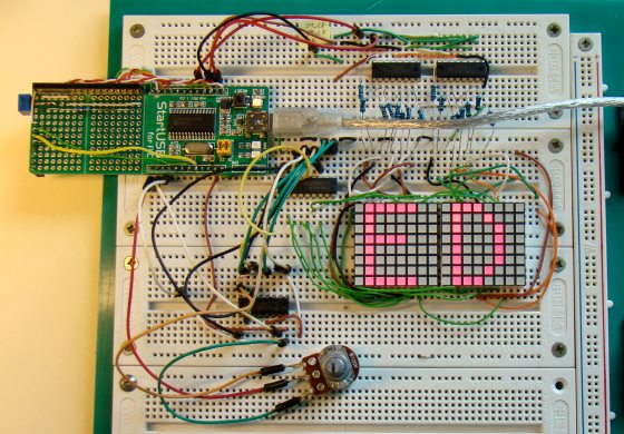
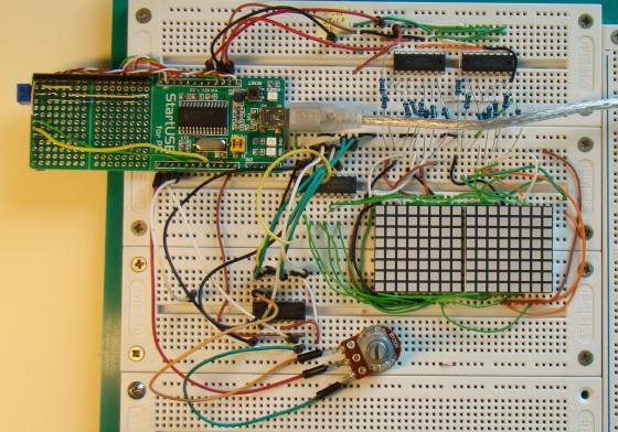
In Lab 12, we learned about the basic structure of a monochrome (single color) LED dot matrix and its interface with a microcontroller to display static characters and symbols. Today’s lab is its continuation, and we will be discussing on displaying a scrolling text message on a 16×8 LED dot matrix. The microcontroller used is again the same PIC18F2550 from StartUSB for PICboard. The 16 columns of the LED matrix are driven individually by two shift registers (74HC595), whereas the eight combined rows are driven by the decoded outputs from a decade counter (CD4017). In Lab 12, columns were scanned, but here we will be scanning across the rows and feed the column lines with appropriate logic levels. An analog input from a potentiometer is read by the microcontroller to determine the speed of the scrolling message. The technique will be demonstrated for right to left scroll, but can be easily implemented for scrolling in other directions. The program for PIC18F2550 is developed with mikroC Pro for PIC compiler.
Circuit Diagram
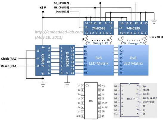
The internal structure of LED dot matrix displays have already been discussed in Lab 12 and is not going to be repeated here. Two 8×8 LED matrices are used in this experiment. The similar rows (cathodes) of both are connected together so that there are 8 combined rows in total, whereas the columns are driven separately, and hence there are 16 columns altogether. The combined current of all the LEDs in each row sinks through a darlington-pair transistor array inside an ULN2803 IC. The 16 column lines (anodes) are driven by the outputs of two shift registers (74HC595) with current limiting resistors (220 Ω) in series, as shown below.
Role of shift registers (74HC595)
The use of shift registers minimizes the number of I/O pins required to drive the columns of the LED matrix. For driving 16 columns separately, we need 16 I/O pins of microcontroller, however, with the use of two 74HC595 ICs, this number is reduced to 3. 74HC595 is an 8-stage serial-in, serial or parallel-out shift register, with a storage register. The shift register and storage register have separate clocks: SH_CP (pin 11) and ST_CP (pin 12). Data is fed serially into the register through DS pin (14) and is shifted on the positive-going transitions of the SH_CP input. However, the data in each register does not appear at the output pin of 74HC595 unless it is transferred to the storage register. This happens on a positive-going transition of the ST_CP input. 74HC595 also provides a serial standard output, Q7’ (pin 9) for cascading, which is needed in this experiment. The serial output of the first shift register is connected to the serial input (DS pin) of the second shift register, so that the 16-bit column data can be transferred serially through the DS pin of the first shift register. This requires 16 clock pulses on SH_CP followed by a clock pulse on ST_CP. The asynchronous reset pin (MR) is always pulled high (deactivated) whereas the output enable (OE) pin is permanently grounded (always enabled).
Role of counter (CD4017)
As mentioned in the beginning of this article, this time the rows will be fast-scanned from the top to the bottom, unlike the columns like we did in Lab 12. Eight I/O pins are required to scan 8 rows in sequence. You can use the PORTB pins of PIC18F2550 for this purpose. But if you think you will need them for some other purpose (some of PORTB pins have interrupt-on- change feature), you can use a port expander, such as CD4017, that will serve the purpose and require only two I/O pins of microcontroller. CD4017 is a 5-stage divide-by-10 Johnson counter with 10 decoded outputs and a carry out bit. The counter is cleared to zero count by a logical “1” on its reset line (15). The counter is advanced on the positive edge of the clock signal (pin 14), when the clock inhibit pin (13) is grounded. The 10 decoded outputs are normally in the logical “0” state and go to the logical “1” state only at their respective time slot. Each decoded output remains high for 1 full clock cycle. The carry-out signal completes a full cycle for every 10 clock input cycles and is used as a ripple carry signal to any succeeding stages. The 8 rows of LED matrix are sequentially connected to the decoded outputs, Q0- Q7, of CD4017 through ULN2803 IC that has eight Darlington pairs, each of which provides a ground path to sink the combined current of all LEDs in a row. At the end of every 8th clock cycle, the microcontroller will reset the counter by issuing a logical “1″ to its Reset pin (15).
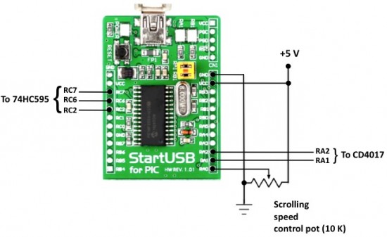
The microcontroller pins used for driving these signals for 74HC595 and CD4017 are shown below. A 10K pot is connected to RA0 pin of PIC18F2550 microcontroller that will control the speed of the scrolling message on the LED matrix display.
Software
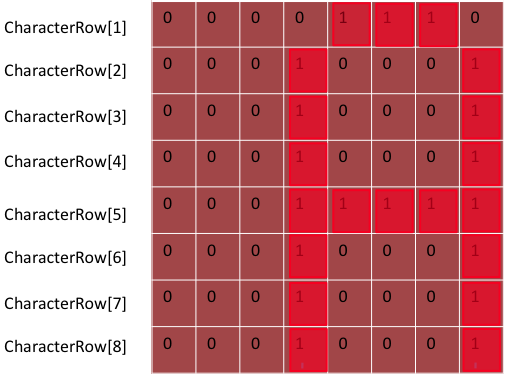
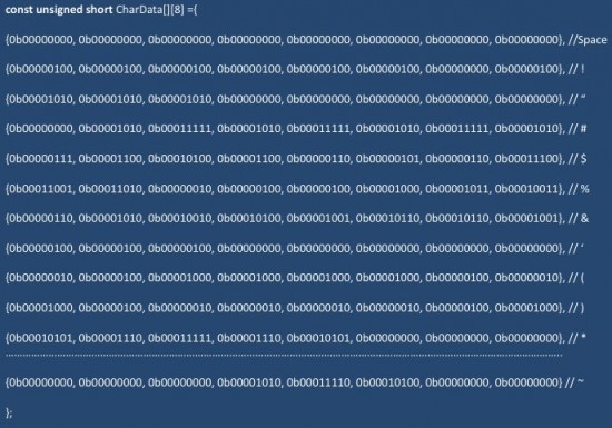
If you are unfamiliar with how static characters are displayed on a LED dot matrix, I would recommend to read Lab 12 first. In row scanning, each row is selected for a very short time (about 1 ms) and the columns are fed with appropriate logic levels. By quickly scanning across the rows (> 100 times per second), and turning on the respective LEDs in each column of that row, the persistence of vision comes in to play, and we perceive the display image as still. The picture below shows the active LEDs in each row to display the character ‘A’ on a 8×8 dot-matrix format. This information for all printable ASCII characters (0-9, A-Z, a-z, etc) will be stored in a two-dimensional constant array CharData[][8] in the program memory of PIC18F2550.
One question: “How would you find the right index of a particular character in this array?” The answer is simple. This array is created sequentially for ASCII characters starting from ‘Space’ (decimal value, 32) to ‘~’ (decimal value 126). So you need to subtract 32 from the ASCII value of the character itself to get the corresponding row index of CharData array. For example, if you want to display a dollar sign, $, its ASCII value is 36 (decimal). If you subtract 32, you get 4, which in fact, is the right row index of $ in CharData array (see above).
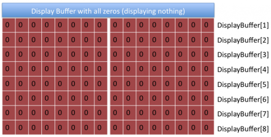
Now lets talk about the scrolling effect. We will also define a display buffer for storing the bit information of 16×8 LEDs in the matrix. It would be an integer array (16-bit) of size 8 (for 8 rows). The content of this array is what displays on the matrix. The picture below shows the bit values of the buffer for blank display, i.e., all LEDs are turned off.
Now lets consider the case of displaying a message that scrolls from right to left. For displaying a character on the matrix, you need to switch among the rows very fast while feeding the column lines with appropriate logic levels (character specific) for each active row. If you want to move the character from right to left, you have to shift the column values for all rows in to left direction with an appropriate amount (Shift Step). Once the character has been shifted sufficiently, you can start feeding the column values of next character in the message. In each shift, you need to update the display buffer. The formula for updating the DisplayBuffer that would create scrolling effect from right to left is,
DisplayBuffer[i] = (DisplayBuffer[i] << ShiftAmount) BIT OR (CharacterRow[i] >> (8- ShiftAmount)
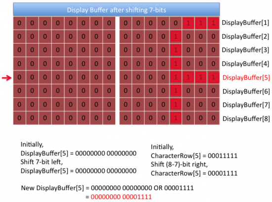
e.g., Suppose, the display is initially blank and you are scrolling character ‘A’ from right, one column at a time. If you see the matrix pattern for ‘A’ in one of the pictures above, you will see that the first three columns from left are all blanks, so nothing would appear on the 16×8 matrix until the fourth column (ShiftAmount = 4) is shifted into the DisplayBuffer. The picture below shows the stage where the initially-blank DisplayBuffer has already been shifted to left by 7 columns (ShiftAmount = 7). DisplayBuffer for row 1 was initially all zeros, ‘00000000 00000000’. The new DisplayBuffer for the first row after the character ‘A’ is partially loaded (up to its 7 columns) is ‘00000000 00000111’. This can be obtained by first shifting the previous value of DisplayBuffer to left by 7, which still gives DisplayBuffer[1] all zeros. The first row of character ‘A’ in an 8×8 matrix format is ‘00001110’. If you shift this right by 8-7 = 1 step, we get ‘00000111’. If you bit-OR this with the new DisplayBuffer[1], you will get ‘00000000 00000111’.
The value of ShiftAmount must be increased sequentially up to 8, after which the 8×8 character is fully loaded in to the display buffer. Then, ShiftAmount restarts from 1 again and starts loading the next character from the right, while the display buffer itself shifts left. This continues until all the characters in the message are loaded.
The following routine serially feeds the two shift registers with a 16-bit column value.
void send_data(unsigned int temp){
unsigned int Mask = 0x0001, t, Flag;
for (t=0; t<16 1="" amp="" apply="" clock="" else="" flag="temp" if="" lag="=0)" mask="Mask" on="" pre="" serial_data="1;" sh_clk="0;" st_clk="0;" t="">
And, the following code does the scrolling of message on to the matrix display. The value ofshift_step determines how many columns you want to shift at a time. I set it to 1.
for (k=0; k (temp >> ((8-shift_step)-scroll*shift_step));
}
speed = 10+ADC_Read(0)/10;
for(l=0; l
You can download the complete mikroC project files for this tutorial from the link below.
References:
Beginning Arduino (book) by Michael McRoberts has a very good description of creating animation on
LED dot matrix display.
ref copy : http://embedded-lab.com/blog/?p=2661
ไม่มีความคิดเห็น:
แสดงความคิดเห็น