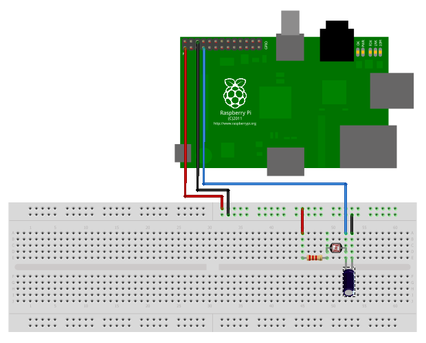
Unlike some other devices the Raspberry Pi does not have any analogue inputs. All 17 of its GPIO pins are digital. They can output high and low levels or read high and low levels. This is great for sensors that provide a digital input to the Pi but not so great if you want to use a sensor that doesn’t.
 For sensors that act as a variable resistor such as LDRs (Light Dependent Resistors) or thermistors (temperature sensors) there is a simple solution. It allows you to measure a number of levels using a single GPIO pin. In the case of a light sensor this allows you to measure different light levels.
It uses a basic “RC” charging circuit (Wikipedia Article) which is often used as an introduction to electronics. In this circuit you place a Resistor in series with a Capacitor. When a voltage is applied across these components the voltage across the capacitor rises. The time it takes for the voltage to reach 63% of the maximum is equal to the resistance multiplied by the capacitance. When using a Light Dependent resistor this time will be proportional to the light level. This time is called the time constant :
t = RC

where t is time,
R is resistance (ohms)
and C is capacitance (farads)
So the trick is to time how long it takes a point in the circuit the reach a voltage that is great enough to register as a “High” on a GPIO pin. This voltage is approximatey 2 volts, which is close enough to 63% of 3.3V for my liking. So the time it takes the circuit to change a GPIO input from Low to High is equal to ‘t’.
With a 10Kohm resistor and a 1uF capacitor t is equal to 1 millisecond. In the dark our LDR may have a resistance of 10Mohm which would give a time of 1 second.
In order to guarantee there is always some resistance between 3.3V and the GPIO pin I inserted a 2.2Kohm resistor in series with the LDR.
Here is the circuit :
Here is the circuit implemented on a breadboard :
 Theory
Here is the sequence of events :
- Set the GPIO pin as an output and set it Low. This discharges any charge in the capacitor and ensures that both sides of the capacitor are 0V.
- Set the GPIO pin as an input. This starts a flow of current through the resistors and through the capacitor to ground. The voltage across the capacitor starts to rise. The time it takes is proportional to the resistance of the LDR.
- Monitor the GPIO pin and read its value. Increment a counter while we wait.
- At some point the capacitor voltage will increase enough to be considered as a High by the GPIO pin (approx 2v). The time taken is proportional to the light level seen by the LDR.
- Set the GPIO pin as an output and repeat the process as required.
Python Code
Here is some code that will print out the number of loops it takes for the capacitor to charge.
#!/usr/local/bin/python

# Reading an analogue sensor with
# a single GPIO pin

# Author : Matt Hawkins
# Distribution : Raspbian
# Python : 2.7
# GPIO   : RPi.GPIO v3.1.0a

import RPi.GPIO as GPIO, time

# Tell the GPIO library to use
# Broadcom GPIO references
GPIO.setmode(GPIO.BCM)

# Define function to measure charge time
def RCtime (PiPin):
  measurement = 0
  # Discharge capacitor
  GPIO.setup(PiPin, GPIO.OUT)
  GPIO.output(PiPin, GPIO.LOW)
  time.sleep(0.1)

  GPIO.setup(PiPin, GPIO.IN)
  # Count loops until voltage across
  # capacitor reads high on GPIO
  while (GPIO.input(PiPin) == GPIO.LOW):
    measurement += 1

  return measurement

# Main program loop
while True:
  print RCtime(4) # Measure timing using GPIO4
Accuracy
Given we only want to spot different light levels we don’t really need to know the resistance of the LDR or the exact time it takes to charge the capacitor. You can do the maths if you want to but I just needed to get a measurement and compare it to some known values. Seconds or Python loop counts, it doesn’t matter.
Python is an interpreted language which means the timing of loops is always going to be affected by the operating system performing other background tasks. This will affect the count loop in our example.
Practical Uses
In a more useful application you can call “RCtime” when you need it to get a count value. Your code can then perform other tasks based on the value of the count, perhaps comparing to values you have measured previously.
When I built my test circuit it was sat in front on my TV. I could see the count number change as the lighting level changed on the TV. It’s so simple you really need to just give it a try!
Acknowlegments
This article was inspired by the excellent article on Adafruit.com.
ref:http://www.raspberrypi-spy.co.uk/2012/08/reading-analogue-sensors-with-one-gpio-pin/#more-520
ไม่มีความคิดเห็น:
แสดงความคิดเห็น